
3D Scene
3D Scene
Starting from v1.14, the large-screen template includes a new 3D model component built on Three.js. With it, you can easily create 3D model display effects.
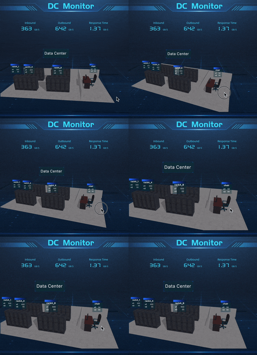
3D Data Center Model Display
3D City Display
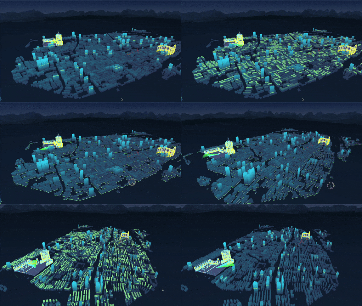
We have implemented the following features from scratch:
- Background Configuration: Supports transparent background, solid color background, skybox (day/night, etc.).
- Camera Configuration:
- Camera position, orientation, FOV, Far.
- Auto rotation.
- Lighting Configuration:
- Ambient light.
- Directional light: position, target, shadows, helper.
- Helpers:
- Axes helper.
- Grid floor helper.
- Models:
- Supports uploading glb, gltf, obj models.
- glb models support draco compressed model parsing.
- Root model supports position, rotation, scale, projection.
- Add model wireframe.
- Ray scanning shader (horizontal, vertical, circular scanning).
- Supports adding labels.
- Supports BI query data label binding.
- Position labels based on matching cross-table data with model names.
- Supports multiple metrics display.
- Supports styling like border, padding, scale, background color.
- Hook function configuration.
- Supports dashboard linkage configuration.
- Linkage can change data in other charts on the dashboard.
- Supports being linked.
- Being linked changes data label content.
Notes Before Use
Before using 3D scenes, you should have some basic knowledge of 3D concepts, such as:
- 3D coordinate system.
- Camera.
- Lighting.
- Models and materials.
- Commonly used 3D modeling software by 3D artists, like Blender, 3ds Max, Cinema 4D, Maya, etc.
- Roles and workflow in 3D projects.
- 3D Artist: Uses 3D modeling software to create 3D models, exports to common formats like gltf.
- Programmer: Loads and parses 3D models exported from modeling software.
- Example: Using Blender to export a gltf model, then loading it via code.
Add 3D Model Component
In the large-screen menu, select Components → 3D Scene to initialize a blank 3D scene onto the canvas. Click the 3D scene to activate the 3D-related configuration menu in the settings panel.
Background
The default scene's Background Type is a black background color. You can configure the background Transparency, change the Background Type to fully transparent None for better integration into the large screen.
Or adjust to a Skybox matching the large-screen theme. The system includes built-in scenes for day, night, and desert.
Camera
Camera Principle Introduction
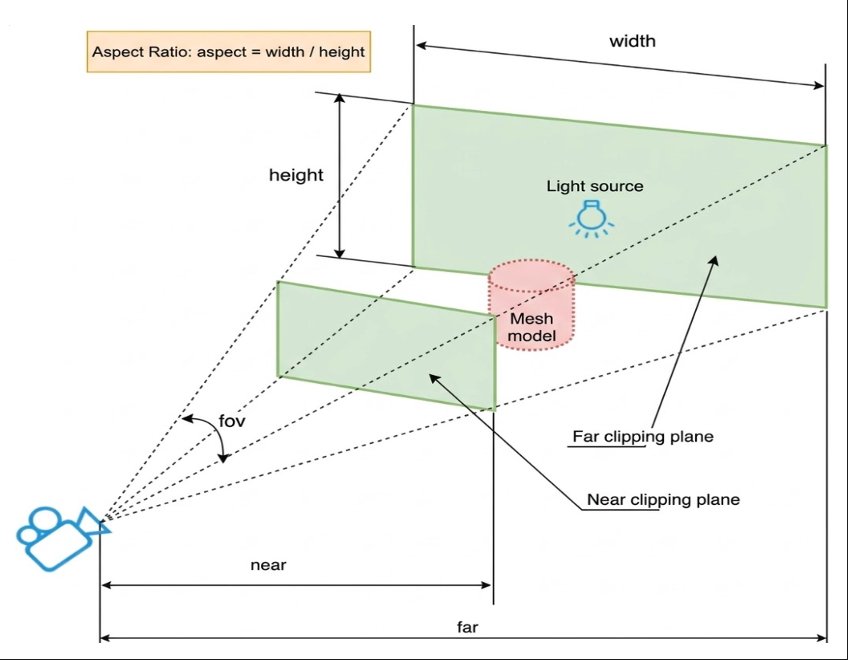
In a 3D scene, the camera can be understood as the medium for observing the 3D model. The default camera position is (-30, 30, -30), looking towards (0, 0, 0), vertical field of view (fov) is 50, and the farthest visible distance (far) is 1000. Objects beyond far are not visible.
Camera Controller
You can rotate the camera and change its orientation using the mouse.
- Left mouse button drag rotates around the target point up/down/left/right.
- Mouse wheel adjusts the distance from the target point.
- Right mouse button drag pans the camera and changes the target object.
After adjusting the camera position, click Get Current Camera Position to update the default camera configuration.
Auto Rotation
Enabling auto rotation makes the camera automatically rotate around the target object for observation. Rotation speed can be adjusted. The up/down rotation range controls the maximum angle for mouse vertical adjustment. Default is 90 degrees, adjustable range 0-180 degrees.
Lighting
Ambient Light
The scene defaults to adding a white ambient light with intensity 1. Ambient light illuminates all objects in the scene uniformly, without distinctions between backlit and lit sides, and does not cast shadows.
Directional Light
If you want effects like sunlight or searchlights, add a directional light. Since enabling shadow calculations has performance costs, the directional light's Cast Shadow is off by default.
Note
Because enabling shadow calculations has performance costs, generating shadows in a 3D scene requires three settings simultaneously:
- Light must cast shadows (enabled in light configuration).
- Object (Mesh like a server rack) must cast shadows.
- Object (Mesh like the floor) must receive shadows.
To easily set which mesh objects cast and receive shadows, I provide configuration properties in the uploaded root model to set shadows via Name Rules. This will be introduced in the model configuration section below.
Light Helper
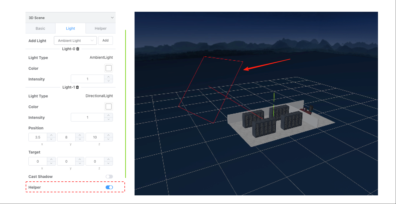
Enabling the light helper shows the light's position and direction in the scene (point lights have no direction).
Helper Configuration
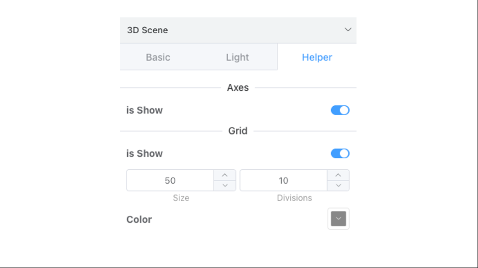
Besides light object helpers, you can also enable Axes and Grid Floor helpers via configuration. Helper configuration is simple and intuitive, so it won't be elaborated here.
Models
Modeling
3D artists commonly use 3D modeling software like Blender, 3ds Max, Cinema 4D, Maya, etc. BI only provides the functionality to load and parse 3D models exported from such software. Modeling is typically done by professional 3D modeling artists.
Model Upload
The current product supports uploading glb, gltf, obj models, and glb models support draco compressed model parsing. Switch to the Models tab in the configuration panel, click Upload Model, select a supported format model file.
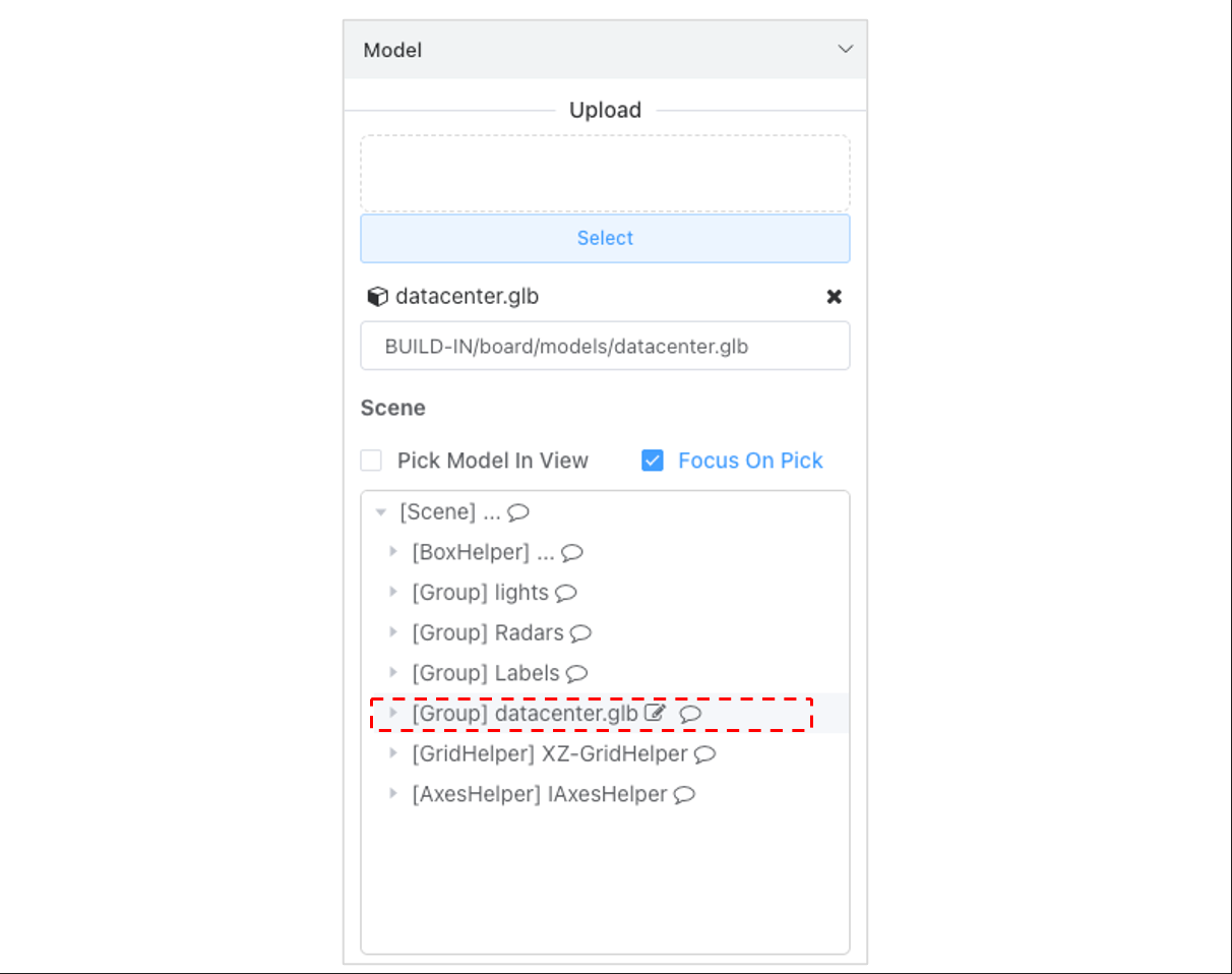
After successful upload and parsing, an object group with the same name as the model file appears in the Scene Structure. The model object corresponding to this file is referred to as the Root Model or Top-Level Model.
Position, Rotation, Scale
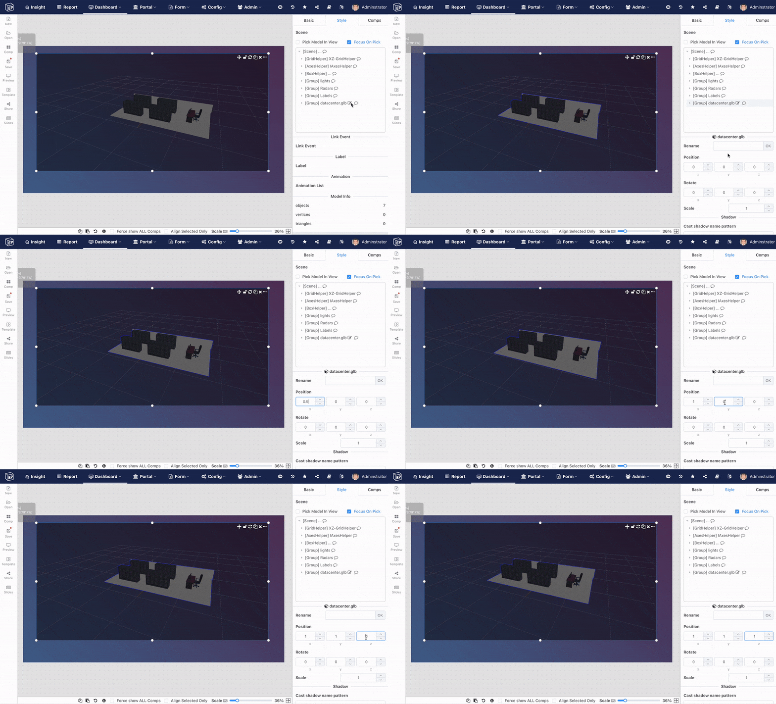
The Root Model/Top-Level Model supports configuring model properties like position, rotation, scale. Rotation angle range is -360 to 360.
Shadow Generation Rules
Recalling from the lighting configuration section, the shadow generation rules are: Because enabling shadow calculations has performance costs, generating shadows in a 3D scene requires three settings simultaneously:
- Light must cast shadows (enabled in light configuration).
- Object (Mesh like a server rack) must cast shadows.
- Object (Mesh like the floor) must receive shadows.
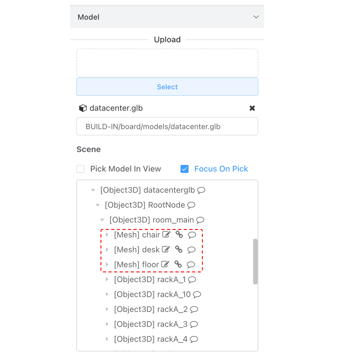
Points 2 and 3: To easily set which mesh objects cast and receive shadows, I provide configuration properties in the uploaded root model to set shadows via Name Rules, as shown below. By setting cast shadow mesh names to body,Desk,chair,
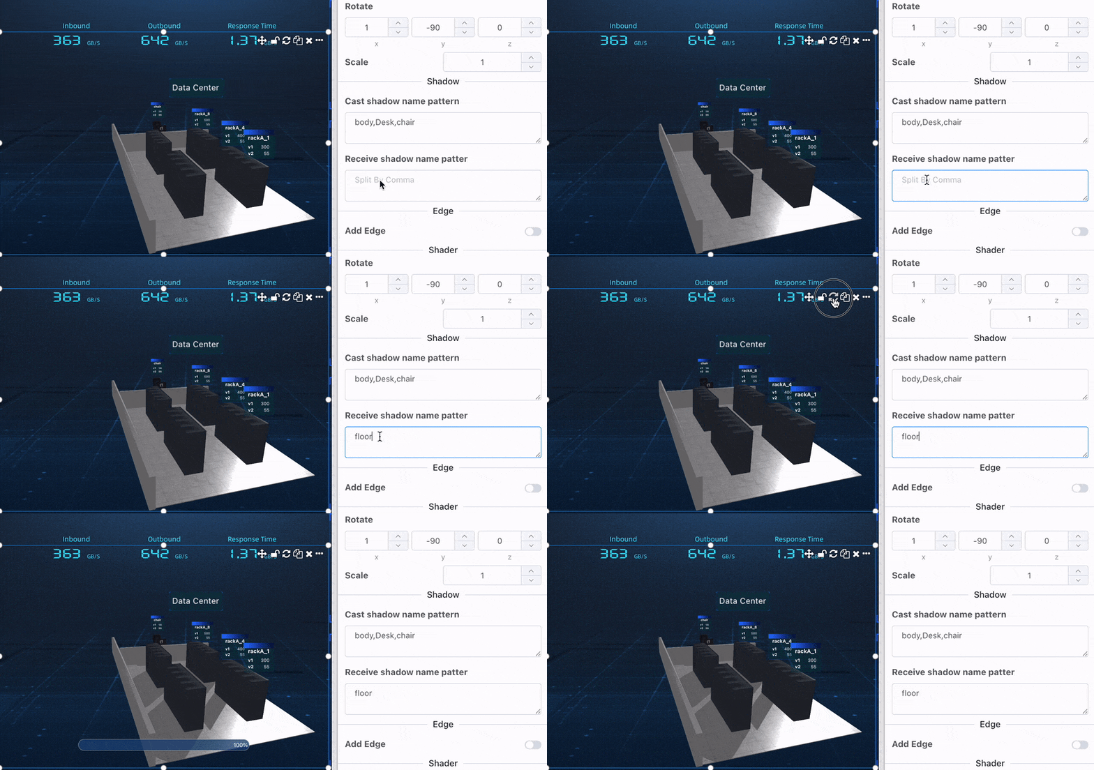
Mesh names are determined in the modeling software and can be viewed in the scene structure tree. Ensure the node type is Mesh. Name matching is case-insensitive.
Add Model Edge
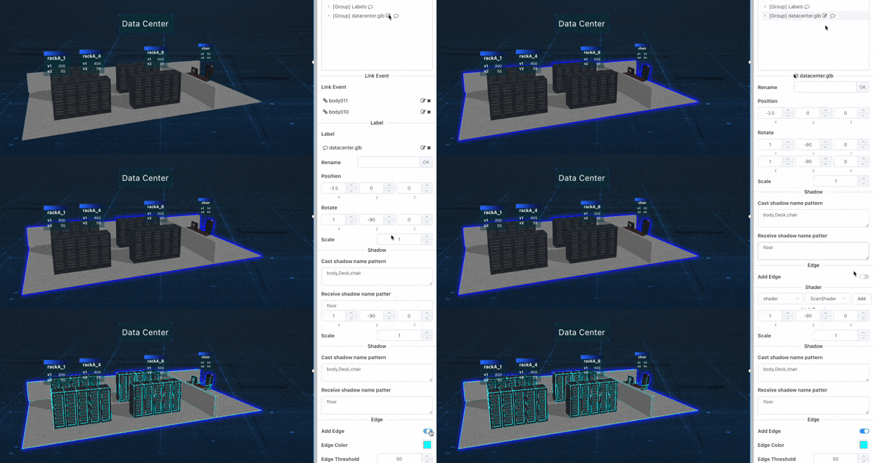
Add edges to the top-level model with one click.
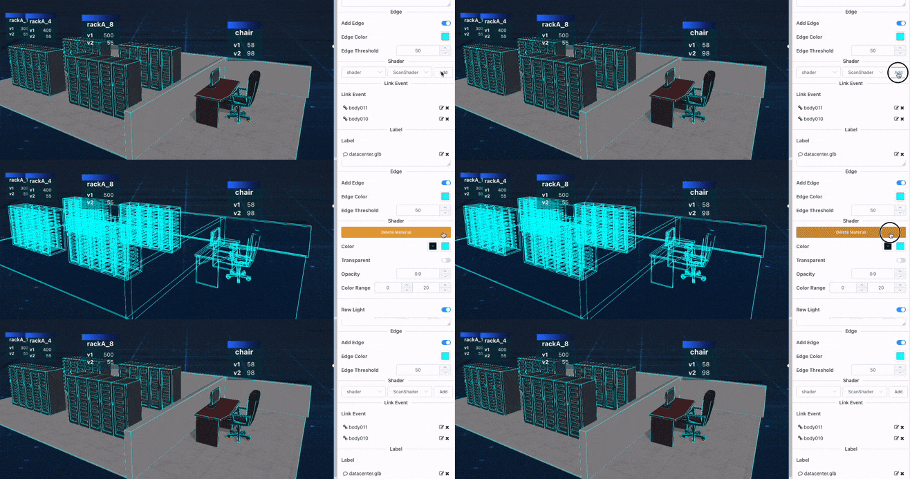
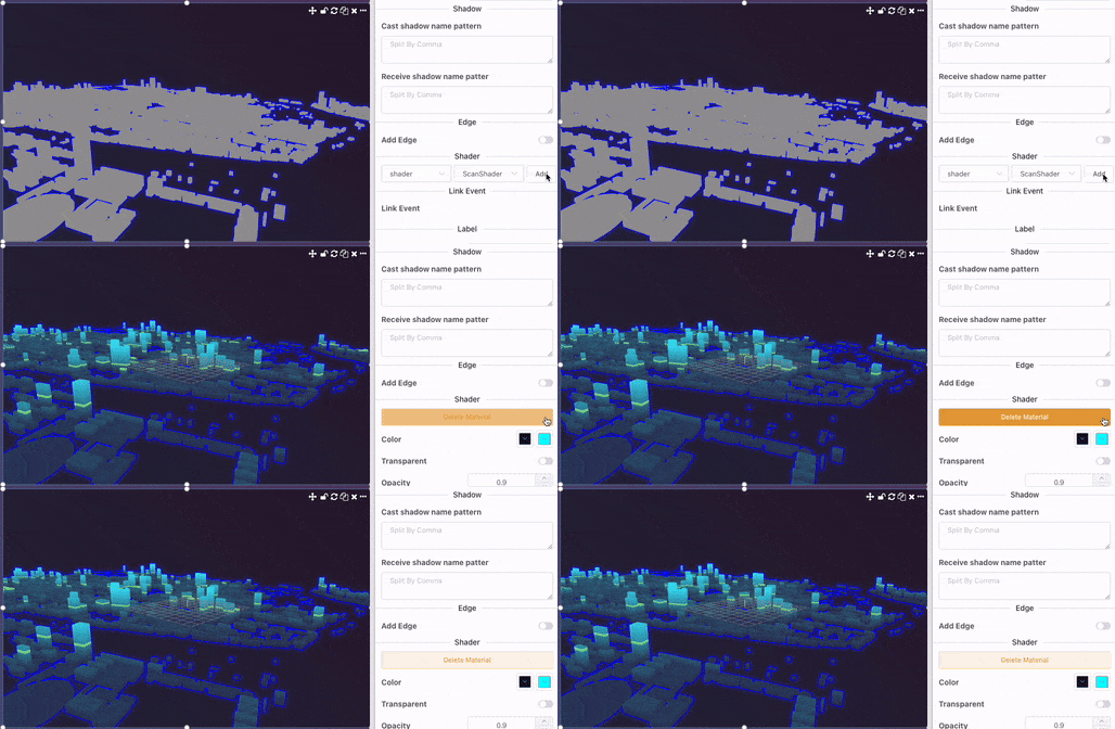
For textured objects, by applying a shader to override the original surface texture, you can achieve a pure color wireframe model.
Ray Scanning Shader
Shader Color Configuration
Note: The gradient color range should match the object's actual height.
Horizontal Light Animation
Can set scan ray width, scan speed, color, and maximum scan height.
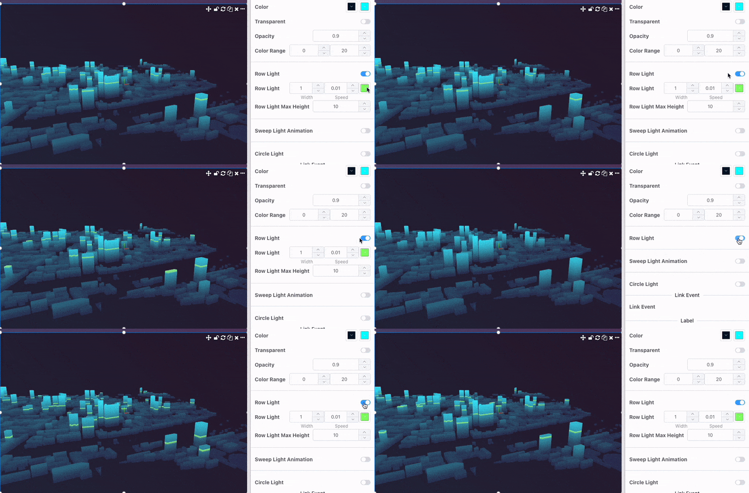
Horizontal Sweep Light Animation
Can set scan ray width, scan speed, color, and maximum scan range.
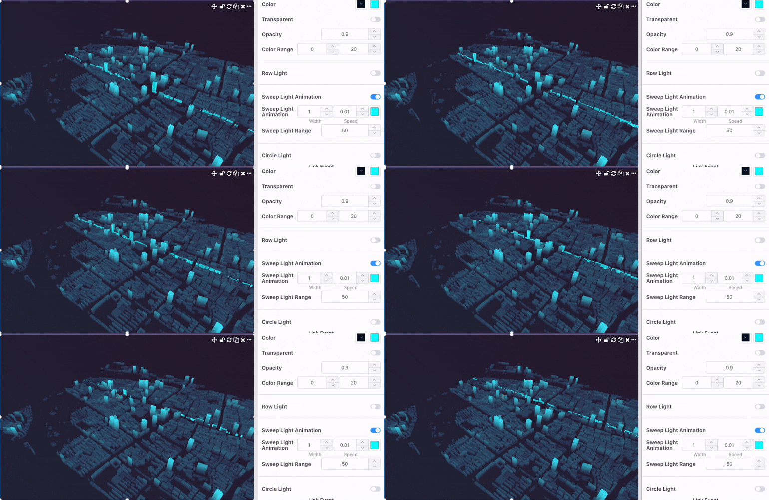
Circular Light Animation
Can set scan ray width, scan speed, color, circle center, and maximum ring radius.
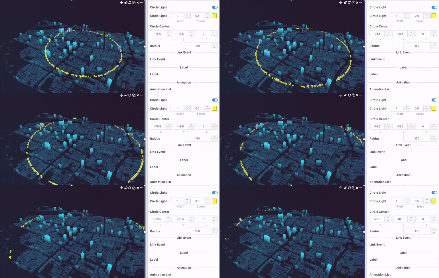
Data Binding
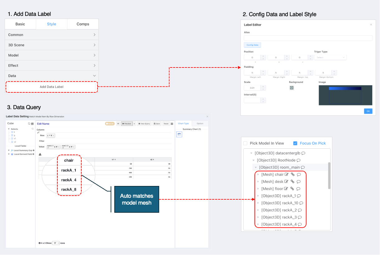
The core of introducing 3D scenes in data visualization is binding with data. To quickly define data queries, we provide a data query definition based on the self-service analysis designer. The steps are as follows (click image to enlarge):
- Click
Add Data Labelor edit an existing data label. - Pop-up defines basic data label configuration.
- Alias: Distinguishes different types of data labels, must be unique within the model.
- Position: Relative offset from the matched model object. Default position is above the model.
- Trigger Type: Defines when a single data label is displayed. Default is always. Options: click, mouse hover.
- Padding: Label inner padding definition.
- Scale: Label size units in 3D scenes align with scene units, often causing labels to be too large. Scaling better matches the scene.
- Auto Refresh: Defines data update interval.
- Border Image: Click to change border image.
- Configure Data:
- Click the Configure Data button to enter the self-service analysis data query interface.
- Drag row dimensions and measures to output cross-table data. The output's row dimensions will be matched with node names in the model. Supports column dimensions and multiple measures.
- After data configuration is complete, click Save Data Configuration to close the data configuration window. Return to the label configuration window and click Confirm. The data label configuration will update automatically.
Static Labels/Annotations
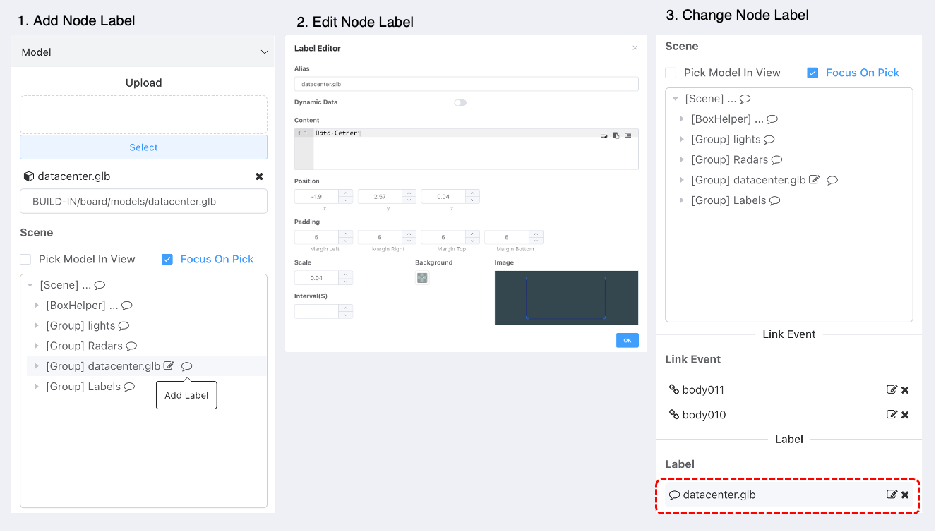
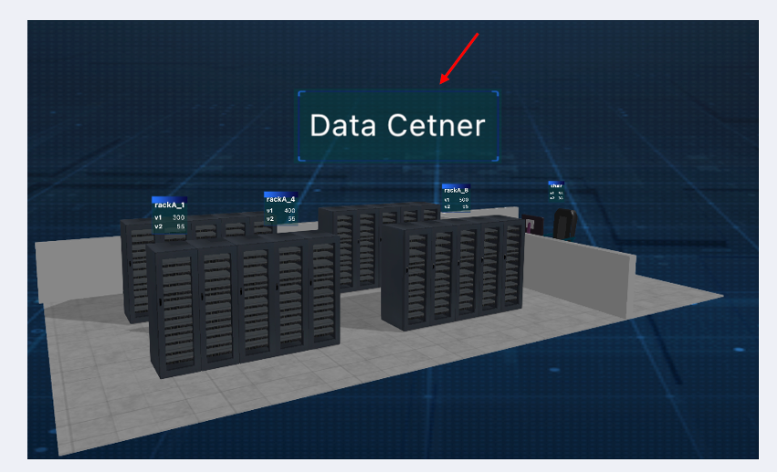
Dynamic data label positions are determined by matching model nodes. Static annotation positions are fixed. Steps:
- Click the Add Annotation button next to the scene structure.
- Pop-up defines basic label configuration.
- Alias: Distinguishes different types of labels, must be unique within the model.
- Position: Relative offset from the matched model object. Default position is above the model.
- Trigger Type: Defines when a single label is displayed. Default is always. Options: click, mouse hover.
- Padding: Label inner padding.
- Scale: Label size units in 3D scenes align with scene units, often causing labels to be too large. Scaling better matches the scene.
- Auto Refresh: Defines data update interval.
- Border Image: Click to change border image.
- Supports configuring dynamic data content.
- Static content supports environment variable parsing.
- Switching to dynamic data content supports API and Query request methods.
- API request requires response data structure:
{text: 'Label Content'}. - Query request displays the
textfield from the first row. If notextfield, uses the first field content.
- Each click on the Add Annotation button in the tree structure creates a new annotation. The button on the tree node is only for positioning. To edit or delete a static annotation, use the label list operations.
Linkage Configuration
Linkage
Linkage can change data in other charts on the dashboard.
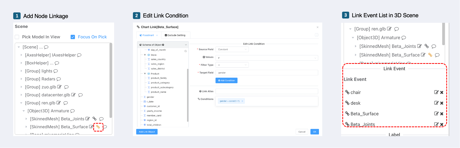
- Since only mesh objects in the 3D scene can respond to click events, linkage events can only be defined for nodes of type Mesh.
- Linkage object configuration is consistent with chart linkage, supporting linkage to datasets, charts, dashboards, environment variables, etc.
- Source field dropdown selects constant.
- After linkage is successfully set, clickable objects are highlighted.
- Clicking triggers the linkage event and the clicked object automatically focuses.
Being Linked
- Being linked changes data label content. The principle: For data labels based on a dataset, when receiving a dataset linkage event, the data label values are updated.
Hook Functions
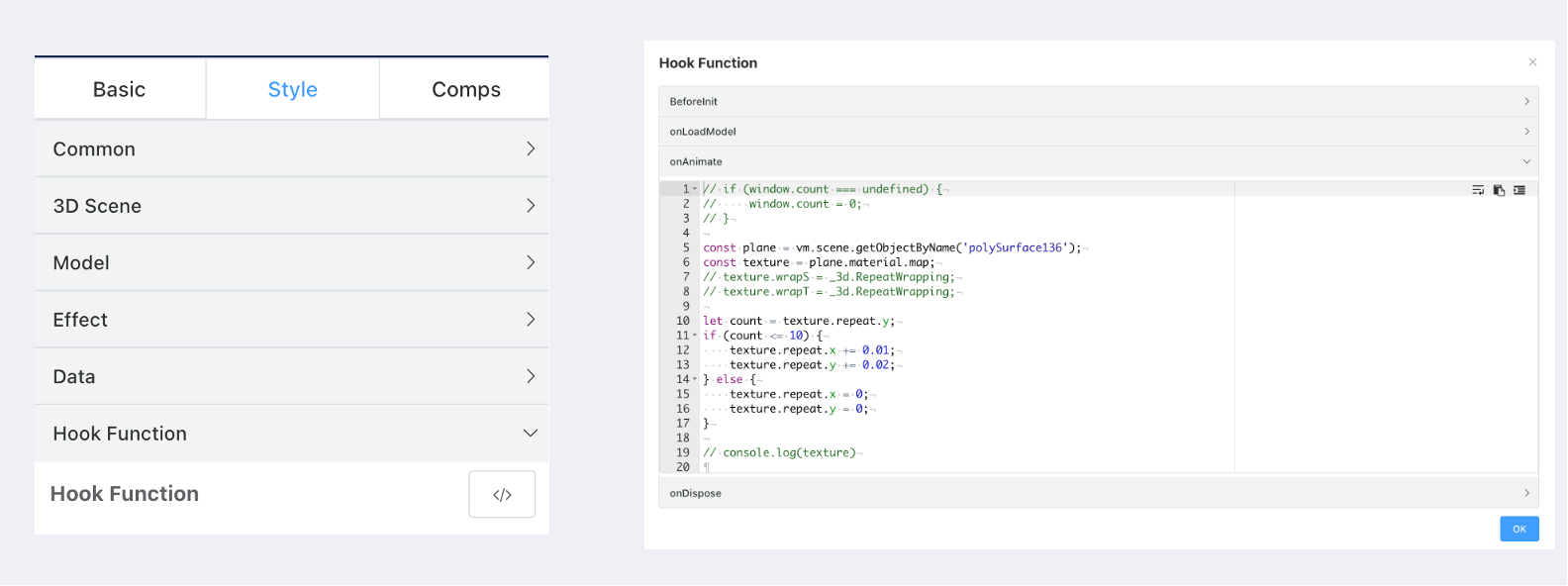
To achieve more personalized requirements, custom code can be inserted at key points:
- Before initialization (BeforeInit).
- When loading models (onLoadModel).
- During updates (onAnimate/on requestAnimationFrame).
- During destruction (onDispose).
Variables Available in Context
- vm: Points to the Vue component.
- _3d:
const _3d = THREE;Points to the THREE library.
Example
Using the following code during frame updates can achieve ground light animation:
const plane = vm.scene.getObjectByName('polySurface136');
const texture = plane.material.map;

let count = texture.repeat.y;
if (count <= 10) {
  texture.repeat.x += 0.01;
  texture.repeat.y += 0.02;
} else {
  texture.repeat.x = 0;
  texture.repeat.y = 0;
}